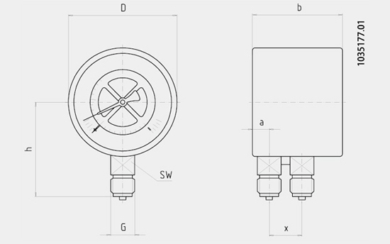
The differential pressure gauge is based on two independently operating Bourdon tube measuring systems. The instrument is therefore able to show the pressure from two measuring points and the resulting differential pressure on one display.
The standard version is designed with two pointers and a gauge pressure scale. The pointer for the minus connection is connected to an additional moving dial. On the scale of the moving dial, the differential pressure (±50% of the main scale's full scale value) can be read directly.
Alternatively, in the version without additional moving dial, the differential pressure is not indicated.
In the version with a subtracting movement, the differential pressure is indicated with only one pointer (the individual pressures of plus and minus connection are not displayed). The variance of scale versions ensures an optimal readabiltiy of all operating parameters.
The models 731.12 and 733.02, with wetted parts from stain less steel, have been specifically designed for the requirements in the process industry.
For harsh operating conditions (e.g. vibration), the instru ments are also available with an optional liquid filling.
Standard version
Version:Two independent measuring systems, process connections in line
Nominal size in mm: 100, 160
Accuracy class: 1.6
Ingress protection: IP33
Scale ranges: 0 ... 0.06 to 0 ... 1,000 bar
Scale range must be selected in relation to the maximum total pressure applied!
In heating systems with circulating pumps, the total pressure applied is usually defined as equal to the hydrostatic pressure plus the pump pressure.
In order to ensure a good readability, the differential pressure should not drop below 1/6 of the full scale value.
When ordering specify both pressures:
a) maximum total pressure applied, b) differential pressure
Pressure limitation
Steady: Full scale value
Fluctuating: 0.9 x full scale value
Short time: 1.3 x full scale value
Permissible temperature
Ambient: -20 ... +60 ℃
Medium:
Model 711.12: +60℃ maximum (soft soldered), +100℃ maximum (brazed)
Model 731.12: +200℃ maximum
Ingress protection: IP33
Process connection
Model 711.12: Copper alloy
Model 731.12: Stainless steel
Lower mount, 2 x G ☒ B (male), SW 22, Plus connection at back, miuns connection at front (identified with ⊕ and ⊝)
Pressure elements
Model 711.12
< 100 bar: Copper alloy, C-type, soft soldered
≥ 100 bar: Stainless steel, helical type, brazed
Model 731.12
Stainless steel, all pressure ranges, welded
Movement: Copper alloy, wear parts argentan
Dial: Aluminium, white, black lettering
Pointer
⊕ side: 1 standard pointer at front, aluminium, black
⊝ side: 1 scale pointer at back, aluminium, red, with 50% of the scale range, respectively, as ⊕ and ⊝ differential pressure display
Case: Stainless steel, black painted
Window: Instrument glass
Ring: Slip-on bezel, steel, black
Options
Other process connection
Case and ring from stainless steel
Design with duplex display ("duplex pressure gauga")
NS 100: Liquid filling (model 713.12)
NS 100: Measuring system, case, ring from stainless steel and liquid filling (model 733.02), medium temperature resistant up to max. 100℃
Subtracting movement (one pointer for differetial pressure display), location of reversed pressure
connection: ⊕ connection at front, ⊝ connection at back, copper alloy or stainless steel
Panel or surface mounting flange
Electrical switch contacts (data sheet AC 08.01), subtracting movement
Dimensions in mm

| NS | Dimensions in mm | Weigth in kg |
| a | b | D | G | h ± 1 | X | SW |
| 100 | 15.5 | 82 | 100 | G☒B | 87 | 32 | 22 | 1.00 |
| 160 | 15.5 | 86.5 | 160 | G☒B | 118 | 32 | 22 | 1.60 |
Ordering information
Model / Nominal size / Scale range / Version of differential pressure display / Process connection / Max. total pressure applied / Size of differential pressure / Options